Platinum Fusion Technology
Saturday, September 23, 2017
Monday, April 14, 2014
Reflowster - Soldering Controller for Surface Mount PCBs by Team Reflows...
I ran accross this on KickStarter, I think it is very neat. Check it out and see what you think.
You don't need to use it just for reflowing, it can be used to turn any 120V device on or off depending on the temperature.
You don't need to use it just for reflowing, it can be used to turn any 120V device on or off depending on the temperature.
Sunday, February 16, 2014
Atmel ATtiny85 with Shift Register
My first successful attempt using a prototype PCB to house electronic components.
There is more I would like to do with this. Though so far I have added an LED to indicated that I have power to the board.
I had to scratch off the middle of the board, between the right and left side. This PCB has each row connected (which I liked).
Here you can see, I have the board powered up. It is currently powered by an FTDI chip for serial communication. I will add an interface for an FTDI breakout, so that it will be eaiser to connect.
I have not shown it yet, but this will be attached to a relay board to control.
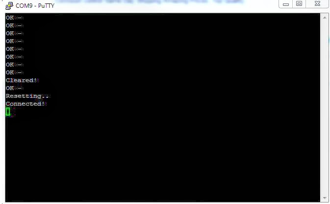
I am now connected to the ATtiny85 chip and comminicating with it.
I shall post my code later, as I continue to work on this project.
Saturday, January 25, 2014
Sunday, December 22, 2013
Adafruit Trinket USB Problem -- Intermittent issues/problems [Solved]
When I first bought Adafruit's Trinket, I was experiencing an issue with my Windows 7 desktop PC.
I could not get my Trinket's red LED to pulsate for 10 seconds after it had power. As it was suppose to do (http://learn.adafruit.com/introducing-trinket/starting-the-bootloader).
Adafruit's Trinket
I finally was able to get the Trinket to work correctly by adding a powered USB hub to my desktop PC. I assume that it may have been a power issue, but I am still uncertain.
Here is the video:
Saturday, December 21, 2013
Adafruit Trinket as an 'Enter' button
 |
| Industrial E-Stop Button |
I am using Adafruit's Trinket to create a simple HID keyboard 'Enter' button.
I started by using the example sketch "TrinketKeyboardExample" and modifying it.
The button is actually an emergency stop button with a normally closed switch.
|
This is the original code "TrinketKeyboardExample":
 /*
 TrinketKeyboard example
 For Trinket by Adafruit Industries
 */
 #include <TrinketKeyboard.h>
 #define PIN_BUTTON_CAPITAL_A 0
 #define PIN_BUTTON_STRING  2
 void setup()
 {
  // button pins as inputs
  pinMode(PIN_BUTTON_CAPITAL_A, INPUT);
  pinMode(PIN_BUTTON_STRING, INPUT);
  // setting input pins to high means turning on internal pull-up resistors
  digitalWrite(PIN_BUTTON_CAPITAL_A, HIGH);
  digitalWrite(PIN_BUTTON_STRING, HIGH);
  // remember, the buttons are active-low, they read LOW when they are not pressed
  // start USB stuff
  TrinketKeyboard.begin();
 }
 void loop()
 {
  TrinketKeyboard.poll();
  // the poll function must be called at least once every 10 ms
  // or cause a keystroke
  // if it is not, then the computer may think that the device
  // has stopped working, and give errors
  if (digitalRead(PIN_BUTTON_CAPITAL_A) == LOW)
  {
   TrinketKeyboard.pressKey(KEYCODE_MOD_LEFT_SHIFT, KEYCODE_A);
   // this should type a capital A
   TrinketKeyboard.pressKey(0, 0);
   // this releases the key
  }
  if (digitalRead(PIN_BUTTON_STRING) == LOW)
  {
   // type out a string using the Print class
   TrinketKeyboard.print("Hello World!");
  }
 }
Here is my modified code:
 /*
 TrinketKeyboard example
 For Trinket by Adafruit Industries
 Modified by PlatinumFusion
*/
#include <Bounce.h>
#include <TrinketKeyboard.h>
//#define button0 0
#define PIN_BUTTON_STRING 2
Bounce button0 = Bounce(0, 10);
void setup()
{
// button pins as inputs
pinMode(0, INPUT_PULLUP);
// setting input pins to high means turning on internal pull-up resistors
digitalWrite(0, LOW);
// remember, the buttons are active-low, they read LOW when they are not pressed
// start USB stuff
TrinketKeyboard.begin();
}
void loop()
{
TrinketKeyboard.poll();
button0.update();
// the poll function must be called at least once every 10 ms
// or cause a keystroke
// if it is not, then the computer may think that the device
// has stopped working, and give errors
if (button0.risingEdge()) {
TrinketKeyboard.pressKey(0, KEYCODE_ENTER);
// this should be the 'Enter' key
TrinketKeyboard.pressKey(0, 0);
}
}
Testing the Button:
Monday, December 16, 2013
Bluetooth Relay Switch Cost
Here is a list of the items I used to create my bluetooth relay switch:
Here is the code that I used: http://platinumfusion-technology.blogspot.com/2014/01/bluetooth-controlled-lamp-with-attiny85.html
- Electical Box - $0.44 - Here - at Lowes
- GFCI Electical Outlet - $16 - Here - at Lowes
- Extension Cord - $1.67 - Here - at Lowes
- Beefcake Relay Control Kit - $8 - https://www.sparkfun.com/products/11042
- ATtiny85 AVR 8 Pin - $3 - https://www.sparkfun.com/products/9378
- Bluetooth Modem - BlueSMiRF - $40 - https://www.sparkfun.com/products/10269
The total cost of this project comes to about $70, but keep in mind that this is the bare minimum material to create a remote relay with Bluetooth . I used a breadboard, so you would need to find a box to put it all together and make it nice and neat. Also, I used batteries to power the ATtiny, Bluetooth, and Relay Switch.
Here is the code that I used: http://platinumfusion-technology.blogspot.com/2014/01/bluetooth-controlled-lamp-with-attiny85.html
Check out the videos!
Bluetooth Controlled Lamp - Youtube
Subscribe to:
Comments (Atom)


